CPU & RAM Management
The CPU manages main memory (RAM) as a direct-access storage medium, distinct from registers which are accessed within a single clock cycle. The memory unit sees a stream of addresses and read/write requests, without knowledge of how these addresses are generated (e.g., via instruction fetch or data retrieval) . To bridge the speed gap between the fast CPU and slower main memory, a cache is often utilized. The CPU ensures correct operation by implementing protection mechanisms to prevent processes from accessing memory segments they do not own.
The bootstrap process is the procedure by which a computer system starts after power is turned on and loads the operating system into main memory. Since RAM is initially empty, the CPU executes a small program stored in EPROM (BIOS/UEFI). This program initializes the hardware, locates a bootable device, loads the bootloader, and finally transfers control to the operating system kernel. After kernel initialization, the system becomes ready for user use.
Basic Hardware
Main memory and the registers built into each processing core are the only general-purpose storage that the CPU can access directly. Registers that are built into each CPU core are generally accessible within one cycle of the CPU clock. The same cannot be said of main memory, which is accessed via a transaction on the memory bus. Completing a memory access may take many cycles of the CPU clock. In such cases, the processor normally needs to stall. The remedy is to add fast memory between the CPU and main memory, typically on the CPU chip for fast access like a cache.
Protection
We first need to make sure that each process has a separate memory space. To separate memory spaces, we need the ability to determine the range of legal addresses that the process may access and to ensure that the process can access only these legal addresses. We can provide this protection by using two registers, usually a base and a limit, as illustrated in Figure 9.1.
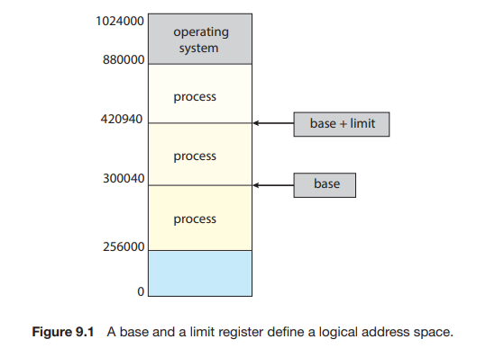
- The base register holds the smallest legal physical memory address.
- The limit register specifies the size of the range.
For example, if the base register holds 300040 and the limit register is 120900, then the program can legally access all addresses from 300040 through 420939 (inclusive).
Hardware Address Protection
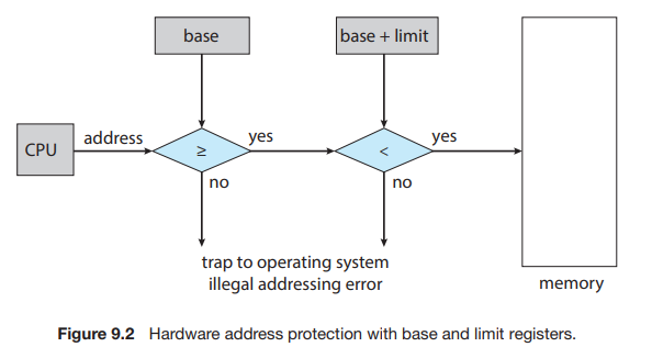
Protection of memory space is accomplished by having the CPU hardware compare every address generated in user mode with the registers. Any attempt by a program executing in user mode to access operating-system memory or other users’ memory results in a trap to the operating system, which treats the attempt as a fatal error (Figure 9.2).
Address Binding
Usually, a program resides on a disk as a binary executable file. To run, the program must be brought into memory and placed within the context of a process, where it becomes eligible for execution on an available CPU.
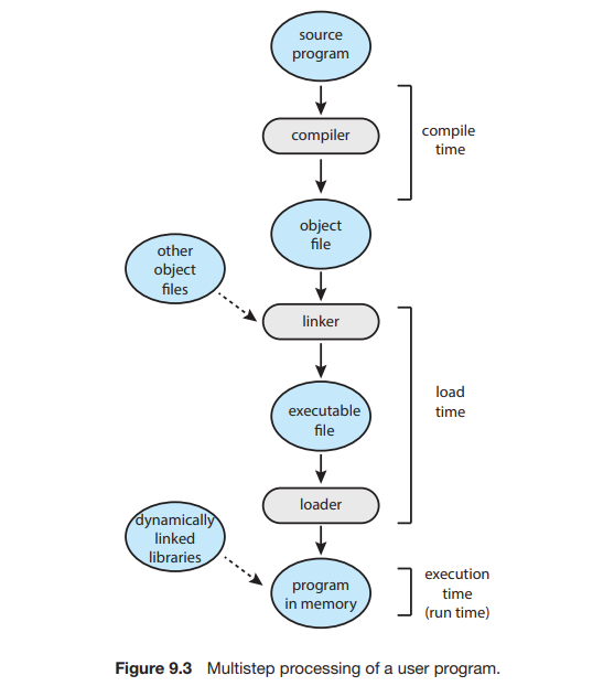
Addresses in the source program are generally symbolic (such as the variable count). A compiler typically binds these symbolic addresses to relocatable addresses (such as “14 bytes from the beginning of this module”). The linker or loader in turn binds the relocatable addresses to absolute addresses (such as 74014).
Classically, the binding of instructions and data to memory addresses can be done at any step along the way:
- Compile Time: If you know at compile time where the process will reside in memory, then absolute code can be generated.
- Load Time : If it is not known at compile time where the process will reside in memory, then the compiler must generate relocatable code.
- Execution time : If the process can be moved during its execution from one memory segment to another, then binding must be delayed until run time.
Memory Management Unit (MMU)
An address generated by the CPU is commonly referred to as a logical address, whereas an address seen by the memory unit, that is, the one loaded into the memory-address register of the memory is commonly referred to as a physical address.
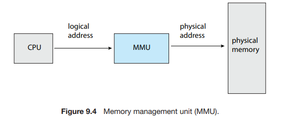
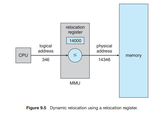
The run-time mapping from virtual to physical addresses is done by a hardware device called the memory-management unit (MMU) (Figure 9.4).
Consider simple scheme, which is a generalization of the base-register scheme. The base register is now called a relocation register. The value in the relocation register is added to every address generated by a user process at the time the address is sent to memory (see Figure 9.5). For example, if the base is at 14000, then an attempt by the user to address location 0 is dynamically relocated to location 14000; an access to location 346 is mapped to location 14346.
Contiguous Memory Allocation
The main memory must accommodate both the operating system and the various user processes. We therefore need to allocate main memory in the most efficient way possible. This section explains one early method, contiguous memory allocation.
The memory is usually divided into two partitions: one for the operating system and one for the user processes. In contiguous memory allocation, each process is contained in a single section of memory that is contiguous to the section containing the next process.
- Fixed Partition: Memory is divided into fixed-sized partitions. The degree of multiprogramming is limited by the number of partitions.
- Variable Partition: Memory is divided into variable-sized partitions tailored to each process’s needs.
Variable Partition
In this variable partition scheme, the operating system keeps a table indicating which parts of memory are available and which are occupied. Initially, all memory is available for user processes and is considered one large block of available memory, a hole.
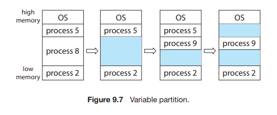
Figure 9.7 depicts this scheme. Initially, the memory is fully utilized, containing processes 5, 8, and 2. After process 8 leaves, there is one contiguous hole. Later on, process 9 arrives and is allocated memory. Then process 5 departs, resulting in two non-contiguous holes.
Dynamic Storage Allocation
The first-fit, best-fit, and worst-fit strategies are the ones most commonly used to select a free hole from the set of available holes.
- First fit: Allocate the first hole that is big enough. Searching can start either at the beginning of the set of holes or at the location where the previous first-fit search ended. We can stop searching as soon as we find a free hole that is large enough.
- Best fit: Allocate the smallest hole that is big enough. We must search the entire list, unless the list is ordered by size. This strategy produces the smallest leftover hole.
- Worst fit: Allocate the largest hole. Again, we must search the entire list, unless it is sorted by size. This strategy produces the largest leftover hole, which may be more useful than the smaller leftover hole from a best-fit approach.
Fragmentation
Fragmentation is a phenomenon in memory management where free memory becomes divided into small, scattered pieces that cannot be efficiently utilized, leading to wasted memory space.
- Internal Fragmentation: Wasted memory inside an allocated memory block.
Fixed Partition = 4 MB
Process Size = 3 MB
Wasted Space = 1 MB (inside the partition)
→ This 1 MB is internal fragmentation
- External Fragmentation: Wasted memory between allocated memory blocks.
Memory State:
[Process A: 100K] [Free: 50K]
[Process B: 200K] [Free: 30K]
[Process C: 150K] [Free: 70K]

Total Free Memory = 50 + 30 + 70 = 150K
New Process needs = 100K

Problem: No single free block is 100K,
even though total free memory (150K) is enough.
→ This is external fragmentation
Paging
Paging is a memory management scheme that permits a process’s physical address space to be non-contiguous. Paging avoids external fragmentation and the associated need for compaction, two problems that plague contiguous memory allocation.
Basic Method
The basic method for implementing paging involves breaking physical memory into fixed-sized blocks called frames and breaking logical memory into blocks of the same size called pages.
Every address generated by the CPU is divided into two parts:
- Page number
- Page offset
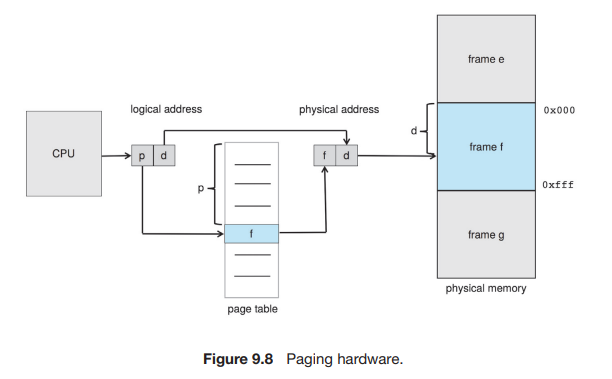
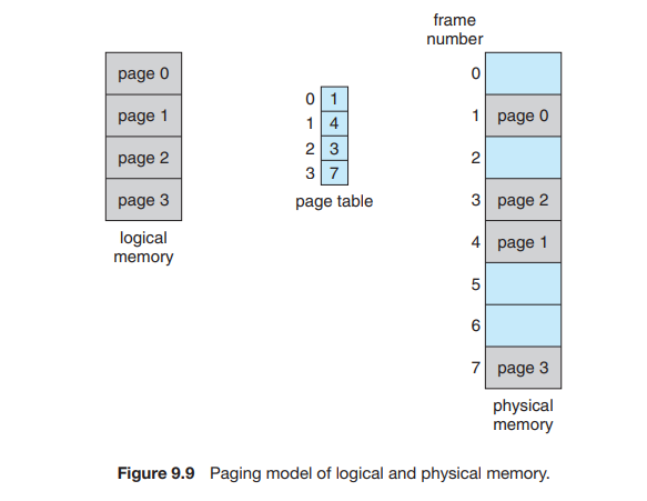
The page number is used as an index into a per-process page table. This is illustrated in Figure 9.8. The page table contains the base address of each frame in physical memory, and the offset is the location in the frame being referenced. Thus, the base address of the frame is combined with the page offset to define the physical memory address. The paging model of memory is shown in Figure 9.9.
The following outlines the steps taken by the MMU to translate a logical address generated by the CPU to a physical address:
- Extract the page number and use it as an index into the page table.
- Extract the corresponding frame number from the page table.
- Replace the page number in the logical address with the frame number .
If the size of the logical address space is , and a page size is bytes, then the high-order bits of a logical address designate the page number, and the low-order bits designate the page offset. Thus, the logical address is as follows:

where is an index into the page table and is the displacement within the page.
Example
Consider the memory in Figure 9.10. Here, in the logical address, and . Using a page size of 4 bytes and a physical memory of 32 bytes (8 pages).
Find the physical address of logical address and .
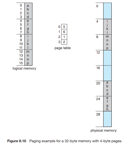
Solution
Formula
Logical address 3
Logical address 4
Logical address 13
Fragmentation in Paging
When we use a paging scheme, we have no external fragmentation: any free frame can be allocated to a process that needs it. However, we may have some internal fragmentation.
For example:
Page size = 2,048 bytes
Process size = 72,766 bytes
Process requires = 35 pages + 1,086 bytes
Allocated = 36 frames
Internal fragmentation = 2,048 − 1,086 = 962 bytes
In the worst case, a process would need n pages plus 1 byte. It would be allocated frames, resulting in internal fragmentation of almost an entire frame.